
Gallery of ZM6 Images
-
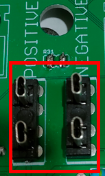
 The lower connector block is equipped with standard 6.3mm spade terminals, allowing for straightforward and reliable electrical connections. The base plate is designed with slotted mounting holes to enhance convenience during installation, making it easier to align and secure the unit in a variety of setups.
The ZM6 is configurable for use with both 12-volt and 24-volt systems, offering flexibility to suit different electrical requirements. It is also compatible with alternators configured as either N or P type, ensuring broad applicability across various automotive and industrial applications. -
 The unit is designed to accommodate a variety of installation needs. It can be mounted either vertically or horizontally, allowing you to choose the orientation that best suits your specific installation requirements.
The case of the unit is constructed from 5052 marine grade aluminium. This material provides excellent durability and resistance to corrosion, ensuring the unit's longevity even in demanding environments. -
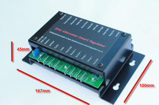 A total width of 167mm x 100mm deep and 45mm height
 -
Showing lower connector block and voltage adjustor on the left
-
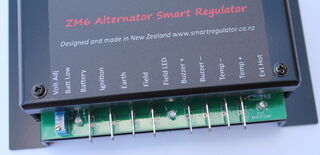
 The matt black decal is designed to clearly display all relevant points of interest, which greatly assists in both the setting process and monitoring during charging operations.
The decal makes it easy to see which LEDs are currently active, allowing for straightforward status checks.
In the event of a fault, the corresponding LED will illuminate. This immediate visual cue enables quick identification and response to any issues that arise. -
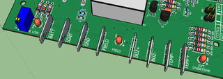 This image displays the arrangement of the spade terminals and the main voltage adjuster. Centrally located among these components is the FIELD LED, which serves as a visual indicator for field activity or status.
 -
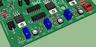 The system features dip switches for setting the absorption time. These allow users to easily configure the required duration for the absorption stage, ensuring optimal battery charging performance.
A ratio adjuster is provided alongside indicator LEDs. The LEDs give clear visual feedback on the current status and settings, assisting in accurate adjustment and monitoring of the charging process.
Push buttons are available to toggle between the absorption and float stages. Users can switch between these two key phases of battery charging as needed. Additionally, a 'CLEAR Fault' button is included for resetting any detected faults promptly.
The system incorporates an over voltage setting, allowing users to set thresholds for voltage protection. A warning LED will illuminate if an over voltage condition is detected, providing immediate visual notification to ensure the system remains within safe operating limits. -
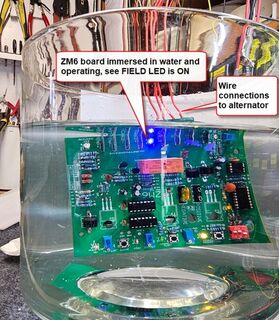 We strongly advise against attempting this demonstration at home. Our aim was to showcase the measures taken to protect the unit against water ingress.
Obtaining an official water resistance certification can be quite costly. Instead, we chose to provide photographic evidence, which often conveys more than words can alone. We invite you to review the image and make your own judgement.
Special thanks to Mrs P for providing the flower vase used in the demonstration. -
 The unit comes equipped with a single 5 amp fuse, designed for installation according to the correct alternator polarity.
If you are unsure about determining the correct polarity for your alternator, support is available. We can provide guidance to help you ensure the fuse is located properly. -
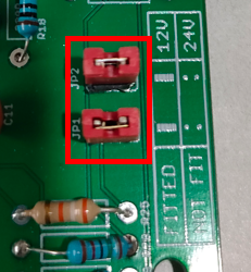 The system is designed to operate with flexibility in its working voltage. Users have the option to configure the system for either 12 volt or 24 volt operation, ensuring compatibility with a range of electrical setups and requirements.
 -
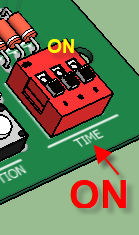 The device is equipped with a DIP switch, which enables users to select the most suitable duration for the Absorption voltage. This selection should be based on the specific battery type and its capacity to ensure optimal performance.
A sticker located on the base of the unit provides clear guidance on the appropriate switch positions. By referring to this sticker, users can easily set the desired timing for their particular battery requirements. -
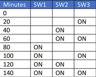 The label provided will display the various possible combinations of switch settings. By referring to this label, users can easily identify which switch positions to select in order to obtain the desired Absorption times.
 -
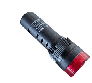 A buzzer or flashing light is provided with the system to serve as a warning indicator for overvoltage or overtemperature fault conditions. This feature is designed to alert users promptly if an issue arises.
It is important to note that if you choose not to install the warning buzzer, you may not be immediately aware if the system trips offline. In such cases, the only indication of a trip event would be the FIELD LED. Relying solely on the FIELD LED may result in delayed response to system faults. -
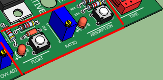 The adjustment of the relationship between Absorption and Float voltage is performed at this stage. Once this relationship has been set, any changes made to the main voltage adjustor will maintain the established ratio between Absorption and Float voltage.
For additional instructions, please refer to the manual supplied with the unit. Alternatively, you can download the relevant documentation from the provided link. -
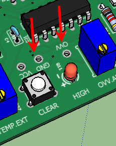 To correctly set the overvoltage trigger, follow the steps outlined below:
1. Connect the Digital Meter:
2. Use a digital meter to probe the GND and OVV points on the circuit.
3. Set Regulator Voltage:
4. Ensure the voltage regulator is set to 14.7 volts.
5. Adjust the OVV Adjustor:
6. While the regulator is at 14.7 volts, carefully adjust the OVV adjustor until the reading is between 5.95 and 6.00 volts.
7. Confirm Overvoltage Trigger:
8. Setting the OVV adjustor within this range ensures that the circuit will trigger overvoltage protection at 15.5 volts. -
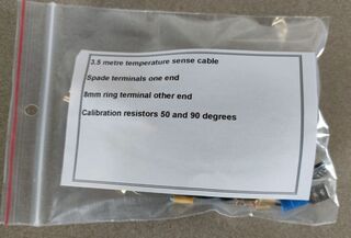 The unit is supplied with a 3 metre cable for convenient installation. It includes an 8 mm ring terminal designed for mounting to the alternator, along with two spade terminals for connection to the ZM6 unit.
Two calibration resistors are provided with the kit, preset for operation at either 50°C for battery monitoring or 90°C for alternator monitoring.
Other temperature settings can be configured by following the instructions detailed in the accompanying booklet.
Longer cable lengths are available upon request to suit different installation requirements.
Comprehensive instructions for constructing your own temperature probe are also provided. -
 The new ZM6 has been subjected to rigorous field testing to evaluate its performance and reliability under varying operational conditions.
Throughout the testing phase, the ZM6 has completed more than 200 start cycles. Notably, one specific test involved switching the device on and off every 20 seconds while operating at a load of 70 amps. This approach was designed to simulate frequent start-stop scenarios and assess the unit's durability under such stress.
In addition to the high-load start cycles, further testing was conducted with the ZM6 performing an additional 5,000 starts at a reduced load of 20 amps. This extended sequence aimed to evaluate the system's consistency and longevity when exposed to frequent activations at lower current levels.
Another aspect of the field testing focused on the ZM6's ability to sustain performance during prolonged operation. The device was operated continuously for 250 hours, drawing 20 amps throughout the duration of the test. This assessment provided valuable insights into the ZM6's thermal management and long-term reliability under a steady load. -
 We maintain a minimum stock of 20 units at all times, ensuring that products are always ready for immediate shipping to our customers.
The basic circuit board for each unit is manufactured in China. Once received, all components are soldered locally, with each board requiring a total of 278 soldered joints. This meticulous process ensures a high standard of quality and reliability in every unit produced.
The aluminium cases are produced locally and are also powder coated here, supporting local industry and providing a durable, high-quality finish to the final product.
Each unit undergoes a rigorous testing process. During manufacturing, products are tested twice using our alternator test rig to ensure functionality and reliability. Following final assembly, every unit is tested once more before being boxed, guaranteeing that only fully functional products reach our customers.